| View previous topic :: View next topic |
| Author |
Message |
Keyell
Joined: 20 Jul 2022
Posts: 14
|
 Posted: Wed Jul 20, 2022 11:44 pm Post subject: Problem with Game doctor floppy drive. Posted: Wed Jul 20, 2022 11:44 pm Post subject: Problem with Game doctor floppy drive. |
 |
|
Hello.
I have a Game Doctor III with a slimline drive and the belt is melted.
I wanted to change the drive to a normal 34 pin drive.
I added the pin headers for a 34 pin drive, changed the power jumper on left side of the board.
I'm getting an RDST error message.
It isn't the power supply. I'm using triad PSUs center negative.
Has anyone replaced the slimline drives with a normal 34 pin floppy drive on this model?
|
|
| Back to top |
|
 |
mrforever
Joined: 19 Nov 2007
Posts: 79
|
| Posted: Thu Jul 21, 2022 9:00 am Post subject: |
|
|
| copy same message in copiers and hardware section
|
|
| Back to top |
|
|
Keyell
Joined: 20 Jul 2022
Posts: 14
|
| Posted: Thu Jul 21, 2022 12:05 pm Post subject: |
|
|
It turns out all the 3 mode floppy drives I have, their controller ICs weren't compatible.
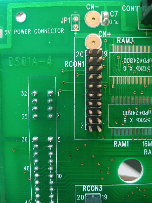
I ripped a floppy drive out of an old Windows 95 computer and it works very well now. For anyone reading this later on, the JP1 jumper needs to be open.
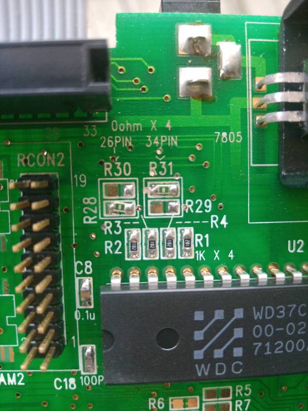
Then there are jumpers near FDC rated at 0ohm that read "for 26 pin" and "for 34 pin". Just remove the 26p jumpers and move them to 34p.
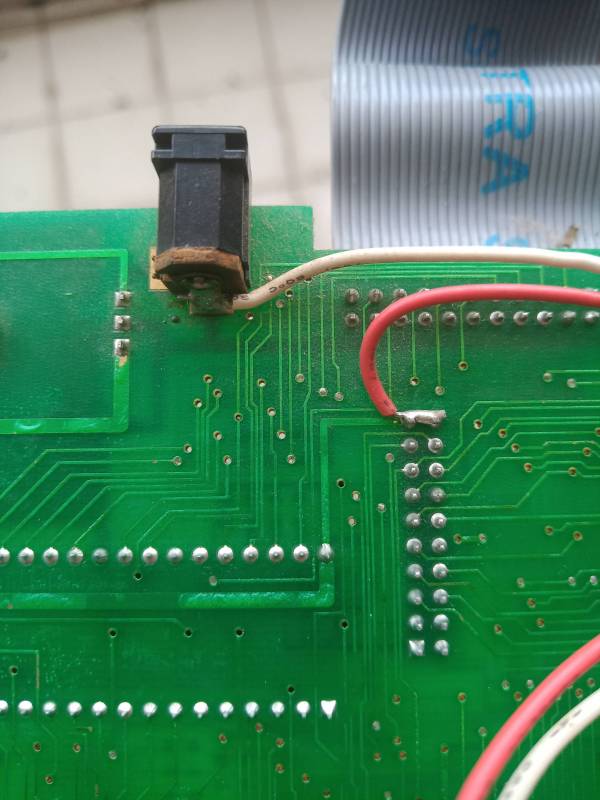
Then solder a floppy power cable on the positive and negative power terminals. Mine were labeled on PCB With - and +
Also it personally blows my mind beyond belief that the first reply to me on a totally dead and outdated forum is to repost this into a different section despite other ancient posts with issues being in this same subsection.
|
|
| Back to top |
|
|
Mystic_Merlin
Joined: 15 Oct 2007
Posts: 508
Location: Bangkok
|
| Posted: Mon Jul 25, 2022 7:34 am Post subject: |
|
|
| Keyell wrote: | It turns out all the 3 mode floppy drives I have, their controller ICs weren't compatible.
I ripped a floppy drive out of an old Windows 95 computer and it works very well now. For anyone reading this later on, the JP1 jumper needs to be open.
Then there are jumpers near FDC rated at 0ohm that read "for 26 pin" and "for 34 pin". Just remove the 26p jumpers and move them to 34p.
Then solder a floppy power cable on the positive and negative power terminals. Mine were labeled on PCB With - and +
Also it personally blows my mind beyond belief that the first reply to me on a totally dead and outdated forum is to repost this into a different section despite other ancient posts with issues being in this same subsection. |
Hello Keyell,
That "dead and outdated forum" is still running and maintained for the sole purpose of sharing FREE information on these machines. I guess you haven't found much elsewhere, did you?
The reason mrforever mentioned that other section is because it's indeed where most people post this kind of request.
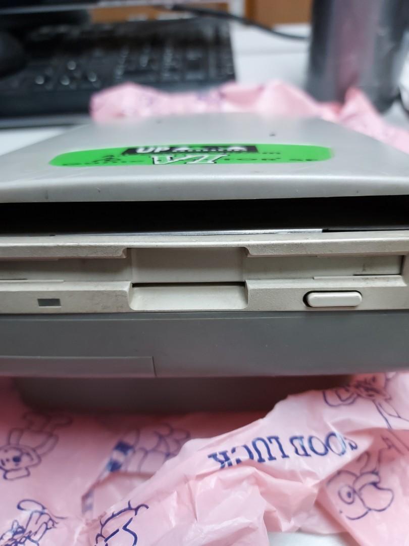
Back to the topic, thanks for sharing your information. I don't think I've seen any GDSF3 sold with a 26p drive. I would guess it's the same Mitsubishi used in the MGD2? So maybe they repurposed them at some point. This would also mean you have a gap in front like that GDSF6?
Anyway, don't throw away this Mitsubishi drive, they're still valuable, that belt can be changed.
| Description: |
|
| Filesize: |
63.52 KB |
| Viewed: |
8331 Time(s) |
|
|
|
| Back to top |
|
|
Keyell
Joined: 20 Jul 2022
Posts: 14
|
| Posted: Mon Jul 25, 2022 1:40 pm Post subject: |
|
|
No that drive is going straight in the trash. Drives with belts don't age well. Eventually the belt will melt or go out again. As with most Mitsubishi FDD, the motor driver IC once the belt melts/breaks will overheat if pushed too much. Any IBM drive should work fine to replace the belt-drives.
There is a gap in the front that is correct. The plastic FDD bezel cover I have covers the entire area though. If it's removed I have the noticable gap.
https://drive.google.com/drive/folders/1mK_iutQ4lpNrCBfSBtv5EPOao0gZRHcV
Also this game doctor... I'm not sure if it's technically a GD3 but the BIOS says GD3. The physical BIOS is not an eeprom but a mask ROM with markings by BUNG inside the case.
Edit: forum is way too limited on image size.
I have uploaded the modification to the GD3. It requires a soldering iron, a floppy power cable (I used DuPont cable instead) and a 34P floppy cable preferably a short one. Just beginner level stuff
Remove jumper JP1. Failure to do this will brick your new drive you add.
I removed the pin headers and added new ones since the 26P type pin headers had some pins clipped. You might be able to just use a floppy cable without removing the pin headers and adding new ones but I didn't try.
Now move jumpers on right side. They're set for 26pin. Set them for 34 pin.
Now solder your power wires on the + and - side of the copier. The insert on FDD.
Add floppy cable and plug it all in.
I was able to format, dump and play a game from disk totally fine.
|
|
| Back to top |
|
|
Mystic_Merlin
Joined: 15 Oct 2007
Posts: 508
Location: Bangkok
|
| Posted: Wed Jul 27, 2022 8:05 am Post subject: |
|
|
Thanks for the drive share but it's more convenient to post photos here for other to access.
Since I had a GDSF3 lying around I took those.
Thanks to Bung for being very thorough labeling everything on their boards, making it self explanatory.
So as mentioned, R31 must be bridged for 34 pin and JP1 not. It's the case as the majority of GDSF3 were sold with a 34p drive, which raise the question as to what is your board serial?
I wonder if it differs from this DS01A-4 and if those were part of a different batch production. The BIOS might also gives an indication as the latest one was the 3.3
| Description: |
|
| Filesize: |
62.69 KB |
| Viewed: |
8286 Time(s) |
|
| Description: |
|
| Filesize: |
63.46 KB |
| Viewed: |
8286 Time(s) |
|
| Description: |
|
| Filesize: |
53.17 KB |
| Viewed: |
8286 Time(s) |
|
|
|
| Back to top |
|
|
Maverick
Joined: 26 Mar 2015
Posts: 15
|
| Posted: Fri Oct 13, 2023 6:36 pm Post subject: |
|
|
| Mystic_Merlin wrote: | Thanks for the drive share but it's more convenient to post photos here for other to access.
Since I had a GDSF3 lying around I took those.
Thanks to Bung for being very thorough labeling everything on their boards, making it self explanatory.
So as mentioned, R31 must be bridged for 34 pin and JP1 not. It's the case as the majority of GDSF3 were sold with a 34p drive, which raise the question as to what is your board serial?
I wonder if it differs from this DS01A-4 and if those were part of a different batch production. The BIOS might also gives an indication as the latest one was the 3.3 |
For GD SF1 is there a way to solder points to make the mod as on the SF3?
Mav
|
|
| Back to top |
|
|
|

