 |
ToToTEK.COM
Help & Support Forum
|
| View previous topic :: View next topic |
| Author |
Message |
Mystic_Merlin
Joined: 15 Oct 2007
Posts: 533
Location: Bangkok
|
|
| Back to top |
|
 |
Trenton_net
Joined: 29 Jun 2006
Posts: 235
|
 Posted: Thu Jul 02, 2009 5:36 am Post subject: Posted: Thu Jul 02, 2009 5:36 am Post subject: |
 |
|
My cousins had copiers which, for some strange reason, couldn't run for more than a few hours before graphics would start to glitch and crash the SNES. In those cases, we just had to let it "cool off" for a bit before we started playing again.
But in your case it's strange because it happens so fast. Though, I can only explain the symptoms. I'm sure there's a more technical reason for extended play not working. In your case, probably more so since it only turns on for a few seconds.
|
|
| Back to top |
|
|
Mystic_Merlin
Joined: 15 Oct 2007
Posts: 533
Location: Bangkok
|
| Posted: Thu Jul 02, 2009 6:01 am Post subject: |
|
|
Thanks Trenton.
Indeed it happens so fast I don't have much time to test anything. I believe the problem is related to that big chip but I don't know if the power issue is caused to it or by it.
I haven't heard of defective chip on copiers but maybe the previous owner damaged it by plugging a bad PSU?
I find weird anyhow that id does work at all if it's been damaged... 
I'll keep searching, keep it coming guys 
|
|
| Back to top |
|
|
Mystic_Merlin
Joined: 15 Oct 2007
Posts: 533
Location: Bangkok
|
| Posted: Thu Jul 02, 2009 7:28 am Post subject: |
|
|
A little update:
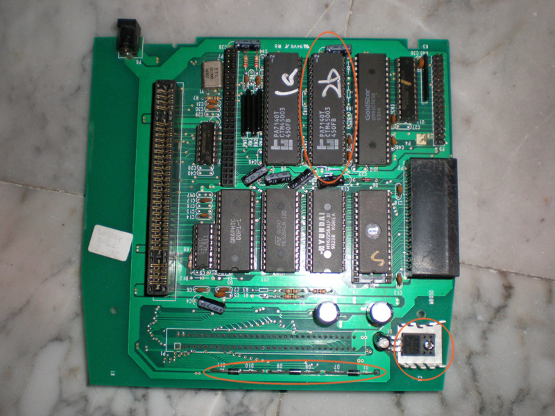
Letting the device rest overnight, when I plug the PSU I get 5.01V from the 7805, after a few secs it drops to 4.30V.
If I switch it on it drops to 3.65V after a few secs.
Then I tried something else, I put some heatsinks on the chip and guess what...I could operate the device for much longer.
Though it's not easy to put the memory board with the sinks below I could read 32M but when I tested the RAM, the copier crashed after 20secs.
So far the conclusion is that this chip does have a overheating problem that causes the copier to crash. All operation that could draw power increase the heating problem...
Should I setup a cryogenic cooling system on it? 
|
|
| Back to top |
|
|
CrackLtd
Joined: 05 Feb 2007
Posts: 239
|
| Posted: Thu Jul 02, 2009 8:28 pm Post subject: |
|
|
| i am no technician, but my first thought were that overheating is caused by feeding to much power. If the rest of the board works ok and only this chip gets to hot there might be one resistor or regulator broken wich reduces power just for this one chip. Maybe its that?
|
|
| Back to top |
|
|
madman
Joined: 07 Jul 2006
Posts: 598
|
| Posted: Thu Jul 02, 2009 8:31 pm Post subject: |
|
|
| 5v is coming out of the regulator and everything on that board is likely a 5v chip, so I doubt it's that.
|
|
| Back to top |
|
|
rodneyk
Joined: 29 May 2009
Posts: 19
|
| Posted: Tue Jul 14, 2009 8:18 pm Post subject: |
|
|
Hi Mystic_Merlin,
From what I read I would suggest two possible causes:
- the chip which overheats is defective
- the chip which overheats is too heavily loaded externally by a short circuit somewhere or by another defective chip which is drawing too much current from it.
I would suggest the following tests:
- test the copier without the Goldstar floppy disk controller plugged in
See if it still overheats. I would suggest that without the floppy controller chip the copier would still switch on and perform all functions except floppy related where it would report floppy disk errors because there is no data output from the floppy controller chip.
- test the copier without the RAM board plugged in
Since the programmable IC might be involved in memory control functions(I don't have any layout photos or scans so I am just writing this without any more details), perhaps the memory chips are involved in the excessive loading of that chip that gets too hot.
RAM is always a vulnerable component in computers and might very well be defective. Whether the copier runs it's ROM program without any DRAM attached or not, you can still leave the copier powered a short while and feel that one chip for overheating without the DRAM board.
- take out all chips to see if there are any bent pins or short circuits underneath such as loose metal parts(screws, small pieces of through hole plating etc) which got stuck somewhere between contacts. Also make sure no capacitors are shorting somewhere. For as far as possible, straighten any components which are not straight. Sometimes bent pins can cause a short somewhere.
It might be possible that a pin is bent somewhere or some metal object got stuck somewhere under a chip.
For example, I once bought a similar copier to this one, the bottom PCB was missing and there were several pins broken off from ICs. I had to repair a lot of things on that one. Some damage was done because someone had unplugged and incorrectly plugged back some ICs.
- Connect the defective programmable IC to it's power supply pins only
That way you can possibly eliminate the fact that the chip is defective itself or it's excessively loaded. The test might be somewhat inconclusive because the chip might behave differently when active. On the other hand, if it overheats without anything connected except the power connections, you might get the suspicion that the chip itself is indeed defective. After all, with only power applied to the chip and no other connections it can't be externally heavily loaded since nothing is connected to it. You could do this test by inserting another IC socket into the chip's socket with only the power pins left inside. Then plug the chip on top so it only gets power applied. Make sure it gets power by measuring the power pins on the chip itself to see if it gets 5V.
With each test you could write down if the programmable chip still gets hot during that specific test.
edit: did you measure the input voltage of the 7805? it's the left pin. As far as I know, the three diodes serve to lower the input voltage of the regulator so it has to dissipate less power in order to drop to 5V output.
I'm curious to see what you find.
Rodney
|
|
| Back to top |
|
|
Mystic_Merlin
Joined: 15 Oct 2007
Posts: 533
Location: Bangkok
|
| Posted: Wed Jul 15, 2009 5:53 am Post subject: |
|
|
Thanks rodneyk! What a nice detailed reply, lots of interesting ideas there
I also have a functional 1.01 version of this copier. Main difference on the board layout are these 3 diodes in serie, maybe I could just switch the defective IC. It should be the easiest testing solution to start with, I was just reticent to do it and potentially damage another IC(?)...
Actually I lifted off the defective IC and didn't notice any shorting or anything suspicious on the board overall
Regarding the RAM, I tested with/without with different boards...same result.
Your idea concerning tests on the ps pins of the IC is interesting. I indeed forgot to probe those.
One thing I forgot to mention also was that the voltage drop is "leveled", it's not a continuous drop, it's like something "trigger" the voltage drop, what kind of component is susceptible to do that?
I'm gonna run some tests and I'll come back with results
|
|
| Back to top |
|
|
rodneyk
Joined: 29 May 2009
Posts: 19
|
| Posted: Wed Jul 15, 2009 5:54 pm Post subject: |
|
|
Hi Mystic_Merlin,
You are welcome.  Ok so we can rule out that it`s the RAM. It`s lucky that the 7805 cuts down the output voltage when too much current is drawn. This protects the copier in this case. Ok so we can rule out that it`s the RAM. It`s lucky that the 7805 cuts down the output voltage when too much current is drawn. This protects the copier in this case.
It might be an option to try the IC that gets too hot in your working copier.
Before you try that however it`s a good idea to check the IC`s value with the other copier and also verfy if the PCB layout around that IC is the same in both copiers. If not the same it might be a bit risky to try it. Putting that chip of your good copier into the one which doesn`t work properly does have a bigger risk to damage the good IC. Regardless what you try both procedures do carry some degree of risk.
Perhaps it`s better to first try my tests before exchanging ICs with the other copier.
What I mentioned about measuring the power pins I meant to make sure that the IC under test which only has the power connections connected in that specific test indeed gets power from the IC socket in between, which only has the power pins present.
I would advise the following tests, where the slight risky one is at the bottom
- test the copier without the Goldstar floppy disk controller plugged in
- test the copier without the IC which gets hot to see if the voltage still drops
- test the `hot` IC with an IC socket in between with only power pins in that socket
(remember to measure during this test that the hot chip indeed gets power supplied
- compare PCB layouts between the copiers and if identical around that chip put the hot chip in the other copier (slight risk so if it gets hot switch off right away)
It`s up to you what you try first. At least there are several options which all might give us some useful information about what causes the overheating.
I repair lots of things for my work so it`s a professional hazard to try to help when I read your story. Just kidding, I just like to preserve this kind of great things like copiers. They are just cool.
|
|
| Back to top |
|
|
Mystic_Merlin
Joined: 15 Oct 2007
Posts: 533
Location: Bangkok
|
| Posted: Mon Jul 20, 2009 10:47 am Post subject: |
|
|
Ok a little update.
The Goldstar FDC is apparently not the problem.
When I take out the faulty IC I get a stable 5V from the regulator.
Here are my measuring results (IC chip oriented as in the photo):
2.3V---------
---------
0.2V---------1V
1.4V---------1V
---------
---------
---------
---------
---------
---------
---------
---------
---------
5V---------
---------
1V---------1v
0.3V---------0.3V
0.4V---------0.3V
5V---------0.3V
Apart from the 5V and some 1V most measurements are irregular, oscillating between 0.1V and 0.4V.
I'm not sure these small voltages are causing the problem but most probably the IC chip is.
rodneyk, which power pins would u reckon I should connect for the tests?
I'll do some measurements on the other copier for comparison.
Do u see anything really odd so far?
As a logic chip I guess it's not replaceable so if it's faulty I believe it's not worth taking the risk to try anything with the other copier. Maybe I'll just switch the BIOS as this more recent version let you test ram and I think keep multiple roms in memory.
|
|
| Back to top |
|
|
rodneyk
Joined: 29 May 2009
Posts: 19
|
| Posted: Tue Jul 21, 2009 10:18 pm Post subject: |
|
|
Hi Mystic_Merlin,
So now we can also rule out the Goldstar FDC chip.
After taking out the hot IC the 5V remains stable.
So we can conclude two options:
- the IC is faulty and when connecting power supply to it, it will get hot and start drawing too much current from the power supply.
- one or more of its outputs are shorted or connected to another part which draws too much current from it or somehow makes it internally short itself.
In order to rule out one of the above options, you need to do the "power pins only" test with the hot IC.
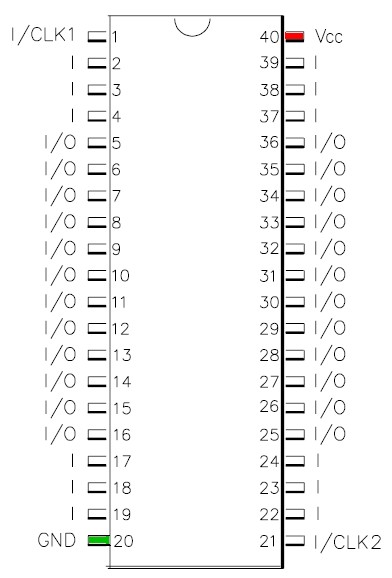
Insert an IC socket on top of the IC socket of the faulty chip, but with only pin 20 and pin 40 connected to it. Try to take out all the other pins of the socket so you are only left with those two pins. After inserting the socket on top, insert the hot IC on top. That way it only gets power supplied and nothing else is connected. Remember to observe correct orientation with the marking on the chip.
Of course, some other way of connecting only those two pins and testing is also fine. Just remember correct connection and rule out shorts, and also remember to use the copier's 5V so you can keep protecting the IC with the 7805 regulator which cuts off at too much current.
I found the datasheet which describes the power connections, please see the picture I took from it. VCC is marked red and GND is marked green. Remember, relative to this picture I took the photo you posted of the copier is upside-down.
When doing the test, make sure to measure those two pins 20 and 40 at the IC itself to make sure the actual IC itself is indeed getting power supplied during the test.
I'll see your findings next time.
About your measurements that you posted, the lower voltages which are not 5V but also not 0V are probably high frequency signals which are constantly fluctuating between 0V and 5V. The multimeter is showing you an interpretation of the average voltage it is seeing over time. So those signals seem to be active ones.
The test above might conclude that the IC is faulty. Of course, it is irreplaceable unless you have the fuse maps for programming a replacement blank chip which is highly unlikely to obtain. This is a problem with these copiers since they can break down and the copier is lost. I am myself now trying to figure out how the supercom/super magicom functions. I am analysing the circuits. If I can figure out the supercom, the step to a SWC is not very big. I hope I can rebuild a copier from scratch. It is my theory that many of the copiers are related to each other in technical basis, evolving into other models developed on the same basic technology. Engineers mostly don't change things much in successive models unless it has some practical purpose.
Exchanging the ICs between the two copiers is indeed risky, it's only an option if you find it worthy, and only after verifying that the layout of the PCB around the chip on both copiers is identical. If there are differences in the PCBs I would not risk that at all in the first place because that might indicate schematic differences related to the programmable logic chips.
Changing the ROM to the other copier might give extra functions but it also might not. It depends if the current hardware of your working copier supports all the ROM functions of the newer one. If some functions controlled by circuits on the copier are missing those circuits they will not work. So that is a trial and error based test, success is based on if the manufacturer only changed the ROM or also some circuits. Also it involves a small risk if the software might cause a logic level conflict between components. If the copier crashes at any time switch it off immediately and don't do any further attempts to exchange the ROMs. I leave it up to you to test this if you find it worth the risk. Again, if the PCBs are identical there is less risk involved.
Another possible test I could suggest, if PCB layouts of both copiers are similar, is putting the older ROM on the copier which gets too hot. Perhaps the ROM on that 'hot' one is causing some logic level conflicts which makes the IC get too hot. Another ROM might solve that.
But this test is only relevant after doing the "power supply only" test to see if the chip itself is ok.
I am suggesting 'optimistic' tests which try to assume that hopefully the programmable chip is not defective. Otherwise it's pointless to try to fix it. If the IC gets hot by itself however, it is simply faulty itself and probably no external influence is at fault. So we have to hope that something else is going on.
| Description: |
|
| Filesize: |
37.49 KB |
| Viewed: |
5948 Time(s) |
|
|
|
| Back to top |
|
|
Mystic_Merlin
Joined: 15 Oct 2007
Posts: 533
Location: Bangkok
|
| Posted: Wed Jul 22, 2009 12:05 pm Post subject: |
|
|
Nice!!!
It's cool to know more people are involved in studying and RE these machines.
Thanks to u, kyuusaku and some other helpful ppl on this board I'm understanding a bit more but between hardware and software there's still a long way to go for me to complete the puzzle...if ever
Anyway don't hesitate to share your findings and ask if I can be of any help with my units.
Regarding the tests, since I didn't have another socket I simply wired the socket to the pins.
The results look odd:
- I get 5V from Vcc-GND on the socket but on the pins of the chip I get around 2V
- the regulator is behaving weird too: It displays 5V then suddenly drop to around 2.5V then go back to 5V and keeps doing that...
I tested the BIOS on the other copier and it seemed to work fine although this one seems to get the regulator quite hot too (with both BIOS).
The main difference I noticed about this 2.02 over my 1.01 is that it does have a HW/RAM test and it displays more information about the ROM loaded. I remember Tomy stating that you need the 2.02 to work with his custom COM PORT adapter.
I'm starting to wonder if this overheating problem is not an issue with this serie. The one pictured above is a later revision and the main difference are the 3 diodes in serie. Maybe they tried to fix the problem this way but still...My guess is that in the long run some other chips could be affected?
Since it's a PFX2 clone, maybe some other people shall know about this issue?
I'll keep my GOOD one running for a few hours to see if I notice some problems.
|
|
| Back to top |
|
|
rodneyk
Joined: 29 May 2009
Posts: 19
|
| Posted: Wed Jul 22, 2009 10:17 pm Post subject: |
|
|
Hi Mystic_Merlin,
It's a bit strange about your test results. I mean, normally speaking there should not be a voltage difference between the power pins of your copier and the power pins at the "hot" IC which you connected with some wires.
After all, the wires have a resistance of at the most a few ohms which means that voltage levels at both sides of the wire should be the same.
If they are not the same, that means that there is some resistance or bad contact somewhere. The high current flowing is causing the voltage drop across the resistance(possibly from bad contacts). It seems the connections might not be very solid. Perhaps you can check them and solder some wires to some solid 5V and GND points at the copier side and make sure they are soldered to the "hot" IC's power pins. That would be the only good way to test this in your situation with the means you have available.
Actually, from what you found we can already conclude now that the "hot" chip is defective and it's not some external influence. After all, if it weren't defective, it cannot still cause the voltage regulator to do strange things like cutting the current because of overloading and putting it back. If the chip itself is in good working order, it should not be able to do these things to the power supply just from connecting the power wires to it.
The three diodes, if I recall correctly their function is very simple, they together lower the power supply input from for example 9V DC to about 9V -(3x0,65) = roughly about 7V. That way, the regulator needs to dissipate less heat to lower 7V down to 5V. As far as I remember they only serve for this function and don't form an essential part except reducing the load for the 7805.
Overheating as much as this "hot" chip does is not normal. It can't be fixed I think. You can check the other copier and feel the same chip in that same socket. It should hardly get warm. Generally speaking, if these simple logic chips do get very warm by design, it's a cheap manufacturing process and the chip will have a shorter life span. But I am sure it's not the case here with your "hot" copier.
I had a quick look at the datasheet just now, it shows that this chip at its maximum load draws about 140-150mA. That's a maximum (worst case). At 5V that means at the most it might generate 0,75W under maximum conditions. That is very little warmth. To shut down the 7805 and get that hot it should take several times 1000mA. Let's say at least about ten times normal maximum operating current. That's not normal. I believe the chip is defective itself. So actually it's somewhat pointless to do any more testing work because it seems that the chip is defective. It's really unfortunate...
About rebuilding a supercom and eventually super wild card and pro fighter, that is just fun for me. I will eventually build a copy of all the normal parts of the supercom on another PCB and put a connector where the custom chip goes in the schematic. Then I will construct many small test circuits to step by step take over the functions of the custom chip. At that stage I can test it in a SNES. But first much more testing to be done to form some theories which circuits can replace the different functions of the custom chip. I also found some old txt file with some useful information about hardware addresses and such of the supercom and super wild card. Several things in that file I have already confirmed in my tests on my supercom to be accurate. I think that the choice of floppy disk controller chip is not entirely critical since it is taken from PC standard. That also explains why some copiers have a Goldstar and some have a Motorola.
|
|
| Back to top |
|
|
Mystic_Merlin
Joined: 15 Oct 2007
Posts: 533
Location: Bangkok
|
| Posted: Wed Jul 22, 2009 11:42 pm Post subject: |
|
|
Thanks again for your great help on this one rodneyk.
You're right about my testing connection not being very solid but I also believe the chip is most definitely the cause, as it was getting very hot.
I tried the GOOD copier and it's been running flawless for hours.
Wow, it's quite out of range for me just to understand the way you could build a copier from scratch but considering there are usually about 16+ custom logic chips on these (PF), the number of possibilities is infinite.
If I understand correctly you could use an original copier and RE every custom chip one by one? Mmm quite a work still!
Talking about FDC, I just noticed something funny about the Pro Fighter serie.
Most copiers were indeed using Goldstar or Motorola FDC. The original Pro Fighter by CCL use a Motorola but the Chinese copy, the Turbo fighter, use an ACC FDC which I believe is a copy of the Motorola. Even the copyright on the bios has been changed from 1993 HK to 1993 R.O.C (Republic Of China)...Copy is really a national sport and pride in China! 
|
|
| Back to top |
|
|
kyuusaku
Joined: 26 Jul 2003
Posts: 941
Location: .ma.us
|
| Posted: Thu Jul 23, 2009 12:26 am Post subject: |
|
|
REing the custom chips isn't TOO much work for most of the chips, most can be thought of complex address decoders. If you know the theory of the parts, you know what part of the system the chips are. One will be connected to the clock and DRAM mux for the state machine, one as random logic coming from the discrete register etc etc. The DRAM state machine should be the only registered logic PLD. It's possible for another to contain a synthesized latch using feedback, but other than that you can watch the outputs of the PLD and deduce the logic.
I think all copier floppy controllers are based on the Intel 8272/8277 and only operate by polling so it shouldn't be too hard to find one to use.
|
|
| Back to top |
|
|
|
|
You cannot post new topics in this forum
You cannot reply to topics in this forum
You cannot edit your posts in this forum
You cannot delete your posts in this forum
You cannot vote in polls in this forum
You can attach files in this forum
You can download files in this forum
|
Powered by phpBB © 2001, 2005 phpBB Group
|